Limit switches
In this section you can find a rectangular object which is preconfigured as a static physics object. Also, the property Neutral while collision is set. This means that the object "notices" the collision with another physical object, but exerts no force on it. In the property section Limit switch settings you can find the property Limit switch operand, where you have to specify the operand to be switched in case of a collision. In this property section you can also select whether the limit switch is to be designed as an opener.
Realize a capacitive, inductive or a color-sensor
The geometric shapes and the limit-switches have the property section named Advanced settings->Physics properties->Collision settings. In this section the property collision group can be set. With this property a material identification and a color identification can be realized.
First some explanations to a collision group: With the help of the collision group it is possible to define, which objects are colliding. The collision group is adjustable in the range 0 to 20. If an object belongs to collision group 0, it collides with all other objects, regardless of which collision group they belong to. If an object has a collision group other than 0, the object only collides with objects in the same collision group.
Example: In the following example the blue rectangle is set to the collision group 2. Sensor S1 has the collision group 1, sensor S2 the collision group 2. The LEDs above the limit switches light up as soon as the respective sensor has triggered.
It can be seen that the rectangle does not trigger sensor S1, because it has collision group 1. So the rectangle belonging to collision group 2 does not collide with this sensor. This is different with sensor S2, which belongs to collision group 2. Its collision group is identical to that of the rectangle. As soon as the rectangle touches sensor S2, the LED lights up as a sign, that sensor S2 has been triggered.
So the blue rectangle could be made of metal and the sensor S2 could be an inductive sensor.
Example: In the next example color sensors are realized. The S1 sensor detects objects with a red colour, the S2 sensor triggers when green objects are detected. This behavior is achieved by assigning sensor S1 to collision group 1 and the red rectangles also belong to this collision group. The green rectangles belong to collision group 2, as does sensor S2.
This results in the following behaviour:
- If the green rectangle touches the sensor S2, it will be triggered, since the two have the same collision group.
- If the red rectangle touches the sensor S1, it will be triggered, since the two have the same collision group.
Conclusion: With the help of the collision groups, sensors can be realized which only react to certain objects. In this way, inductive, capacitive and colour sensors can be implemented in PLC-Lab.
Tip:
Further explanations of collision groups can be found in the following section: Using collision groups
Limit switch changes collision group
As of version 1.5.1.0, a limit switch (or a geometric physics object) can be set so that the collision group of the colliding object is changed in the event of a collision. The two properties "Limit switch changes collision group" and "New collision group on collision" have been added.
The functionality is activated using the "Limit switch changes collision group" property. You have to specify the new collision group to be set in the "New collision-group when collide" property. The entry is made as a constant or variable, e.g. using a word operand (e.g. IM.MW2). When an object collides with the limit switch, the object is assigned to the new collision group. When a body consisting of several objects collides with the limit switch, then all objects of the body are set to the new collision group which belong to the collision group of the object that collides with the limit switch.
Example: A body consists of 4 objects. Two objects belong to collision group 1, the rest to collision group 2. Now an object of collision group 1 collides with a limit switch. Now only the collision groups of the two objects with collision group 1 are changed. The other two objects remain in collision group 2.
You can find more information about collision groups and the change of the collision group in case of a collision with a limit switch in the following section: Using collision groups
Tip:
Every geometric physics object can be configured as a limit switch. All you have to do is select or assign the relevant properties in the property section "Limit switch settings".
Distance sensors and sensors for detecting the height/width of objects
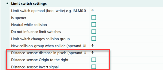
As of version 2.1.0.0, any geometric physics object (rectangle, ellipse, etc.) can be parameterized as a distance sensor. The parameters required for this are located within the "Limit switch settings" section of the objects.
Appearance of the distance sensor in draw mode
If a physics object has been parameterized as a distance sensor, it will have the following appearance in drawing mode.
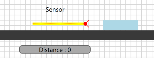
In the image, a fixed rectangle (physics) is parameterized as a distance sensor by specifying an operand at the "Distance in pixels (write operand UInt16)" property. The property "Neutral while collision" is set automatically because the objects to be detected must enter the distance sensor. On the left side of the sensor a red arrow and a red circle can be seen. These symbolize the origin (or zero point) of the sensor. The origin can be changed via the "Origin to the right" property. In this case, the symbols are displayed on the right side of the sensor. In the center of the sensor there is a dashed line, this symbolizes the laser, which takes the measurement. The measuring point is therefore in the center of the object. When the simulation is started, these symbols are removed and only the rectangle is visible.
In the following, the setting options of the distance sensor will be described.
Property: Distance in pixels (operand-UInt16-write)
Here you can specify the operand in which the determined distance is written in pixels. It must be at least a byte operand if the determined distance is in the range 0-255. Normally a word operand must be specified. The max. distance depends on the length or width of the object. For example, if the object has a length of 100 pixels, then the sensor delivers values from 0 to 100.
Example
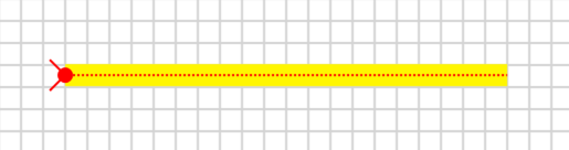
In the following example, the yellow rectangle is set as the distance sensor. A word operand with the "Distance" symbol has been specified in the "Distance in pixels" property. The yellow rectangle has a width of 100 pixels and can therefore supply the value 0 to 100. The origin of the sensor is on the left, this is symbolized by the red arrow and the red circle.
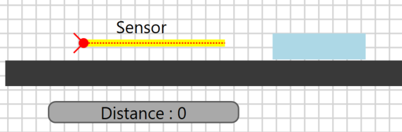
In the picture you can also see that there is a dashed line in the middle of the sensor. The measurement signal is detected at this line. Now the simulation is started and the blue rectangle is pushed into the sensor. As a result, the sensor delivers smaller and smaller distance values.
As soon as the blue rectangle touches the origin of the sensor, it returns the maximum value.
Scale value
If the sensor of the real plant delivers a value from 0 to 1000, then the sensor in the virtual plant does not have to be drawn 1000 pixels wide. Because the value at the property "Distance in pixel" is scalable. For this purpose, the desired range is simply specified in front of the operand. This can be seen in the following:
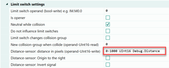
Thus the sensor delivers the values 0 to 1000, although it has only a width of 100 pixels.
Scaling can thus be used to generate the signal present in the real plant without having to change the width of the sensor in the virtual plant.
Property: Origin to the right
By default, the origin of a distance sensor is on the left side. This can be changed via the "Origin to right" property without having to rotate the object. If this setting is made in the above example, then the change is immediately apparent in drawing mode.
You can see that the symbols for the origin are placed on the right side of the object. This is where the origin or the zero point is located.
Property: Invert Signal
If an object on the opposite side of the origin penetrates the sensor, then the sensor provides the distance to the penetrating object.
If you want to capture the height or width of an object, you would have to subtract the delivered distance value from the maximum value of the sensor to get the result. However, this can also be achieved via the "Invert signal" property. If this property is selected, then the indentation depth is supplied as the result from the sensor.
This setting is thus to be used if not the distance but the height/width or the indentation depth is to be determined via the sensor.
Example 1 for distance sensor
In the following example, metal parts are inspected for defects. The metal parts must have three metal pins, which have a certain height. The metal pins have a height of 40 mm, 20 mm and 40 mm. The metal pins are always placed in the same position. The height of the metal pins is determined by a vertically mounted sensor. A horizontal sensor detects the position of the metal part and thus triggers the measurement. The parts are transported to the measuring station via a conveyor belt. The arrangement can be seen below.
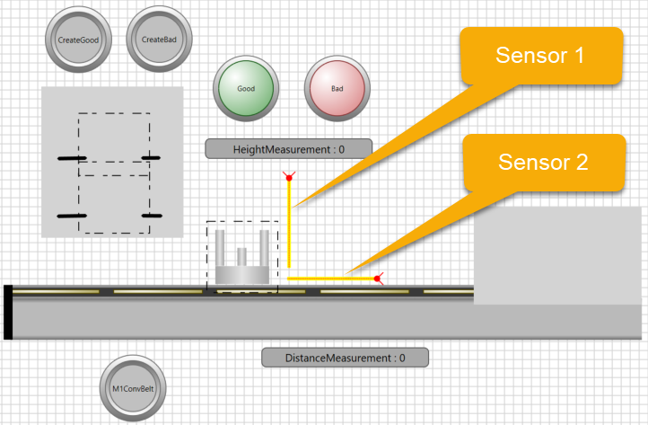
Sensor 1 detects the height of the metal pins, for this purpose the property "Invert signal" was selected in the distance sensor. Sensor 2 detects the position of the metal part and initiates the evaluation of the value supplied by sensor 1. The two lamps are used to signal whether the part is good or bad.
Example 2 for distance sensor
In the next example, parts are transported on a conveyor belt. The correct position of the parts on the conveyor belt is to be checked via a distance sensor B3. If the position of a transported part is correct, then the sensor supplies a value of 37. The measurement takes place as soon as sensor B1 is actuated. In case of an error, the value of the distance sensor is exceeded or fallen short of. In this case, the two cylinders should extend and bring the part into the correct position. The extension of the cylinders is triggered by sensor B2. The following is the structure of the system:
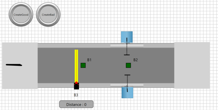
The next illustration shows the process in the simulation.