Device PLCSIM S7-1200/1500 in the Siemens TIA Portal
In the following example, a system is created and used to test a PLC program for a Siemens S7-1200/1500. The PLC program is to be processed in the PLCSIM S7-1200 or PLCSIM S7-1500 in the TIA portal.
Info
Note: If the TIA Portal was started as administrator, PLC-Lab must also be started as administrator. The two programs must therefore have both the same access rights.
Starting PLC-Lab and creating a system
PLC-Lab is started and a new system project is created:
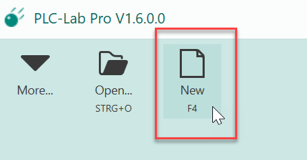
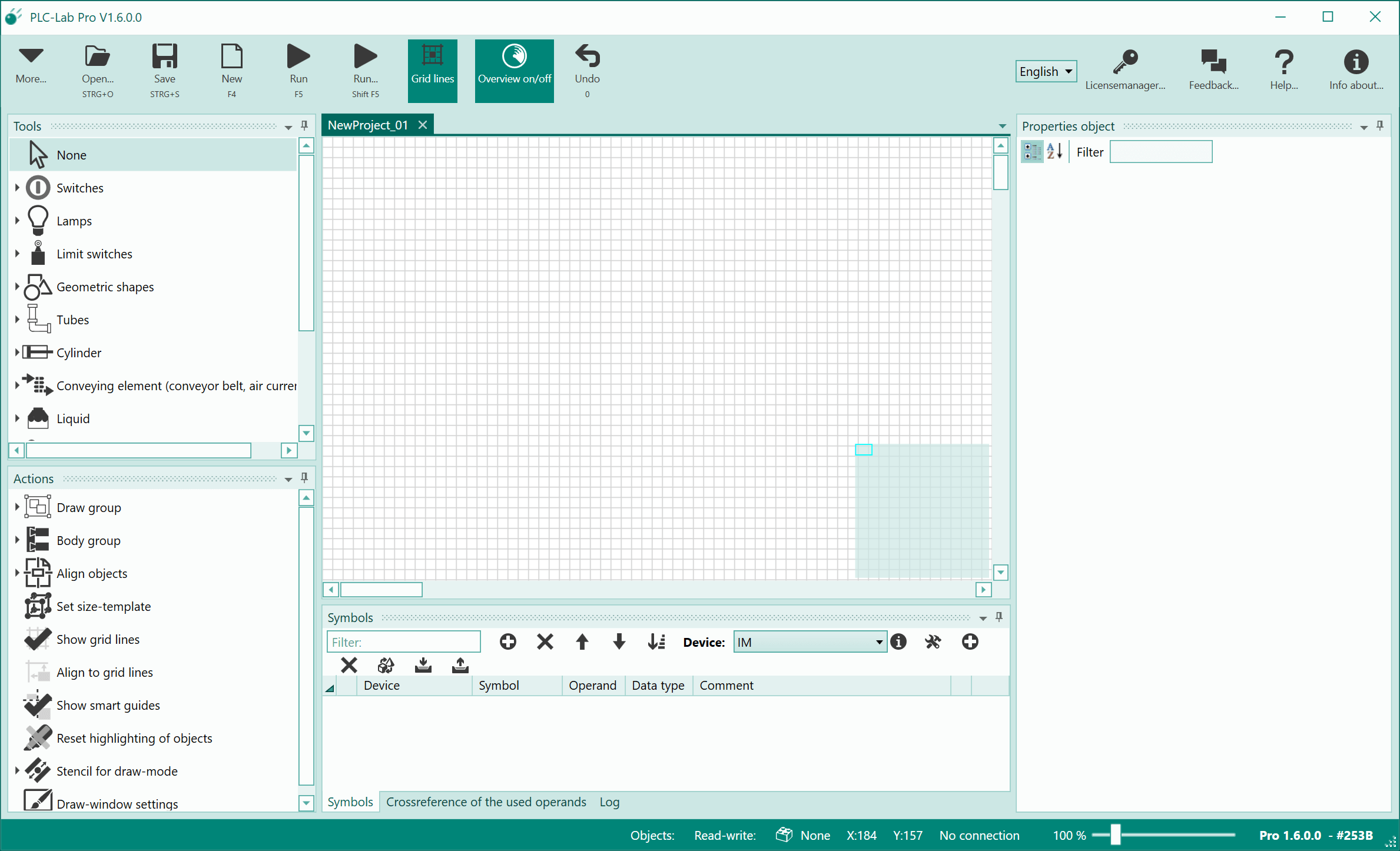
Shortly after pressing the "New" button, the PLC-Lab program window with the drawing board appears.
Selecting a device and creating symbols
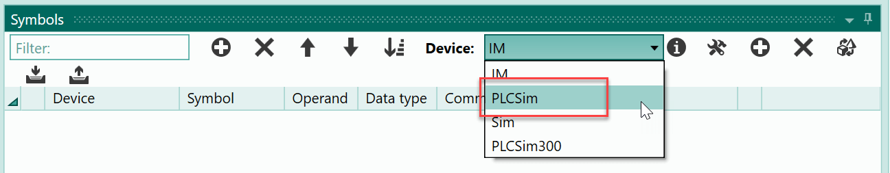
For this example we need three operands, which have to be created in the symbol table first. The operands should belong to the PLCSIM 1200/1500. For this reason, the device "PLCSim" must be selected in the upper part of the symbol table:
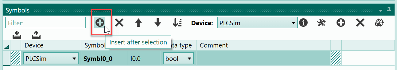
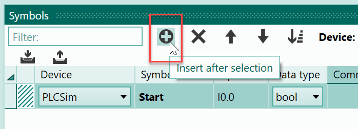
Now all operands added to the symbol table are assigned to this device. The first operand is added to the symbol table by clicking the plus button.
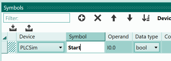
The symbol of the operand is to be changed to "Start". To do this, click on the cell of the symbol.
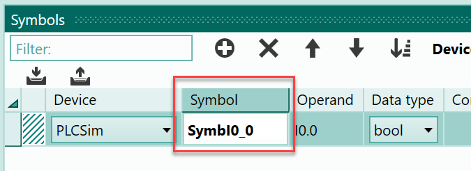
and enter the name.
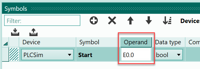
Use the TAB key to jump to the next column of the symbol table. Here you can specify the operand.
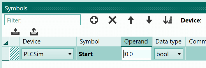
Use the E0.0 as the operand, which is already specified, but with the English syntax: I0.0. You could leave the operand as it is. If you want to use the German syntax, the "I" must be replaced with an "E". You can see this below.
This change causes the German syntax to be used when the next operand is added following E0.0. To insert the next operand, press the button with the plus sign again.
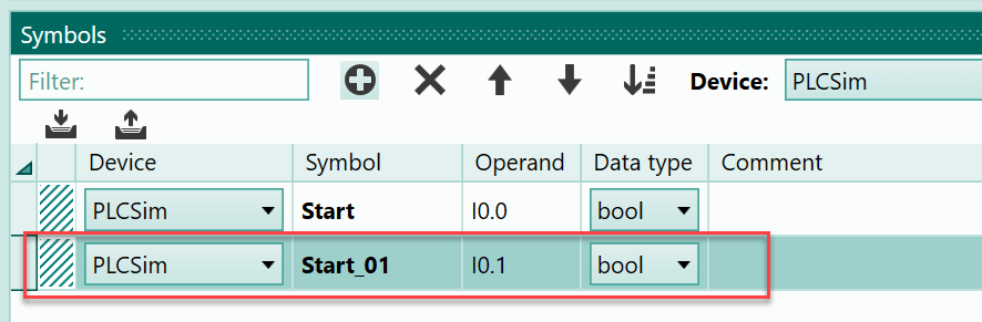
Now there is another operand in the symbol table behind the currently selected operand. Its address is increased to such an extent that there is no address overlap. With a bit operand, this means that the bit address is increased by one.
The standard symbol of this operand should also be replaced by another symbol; specify the symbol "Stop".
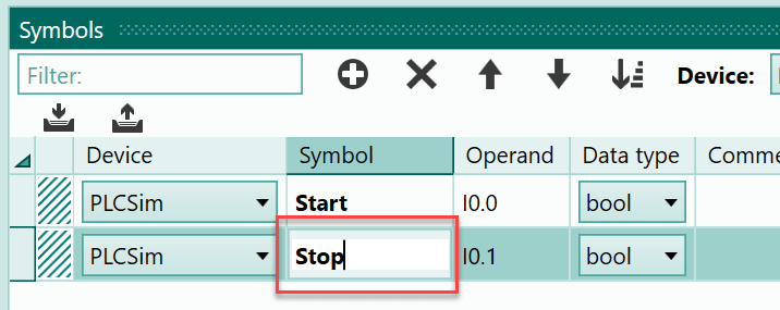
The operand itself is correct: it is input I0.1 and the syntax can be left as it is.
Finally, we need the output Q0.0, to which a lamp is connected. This lamp lights up when the controller is switched on. Now you select the second line of the symbol table (if not already selected) and click the plus button again. Then you can enter "LampStart" as the name of the symbol. These steps are shown below:
Drawing the first push-button
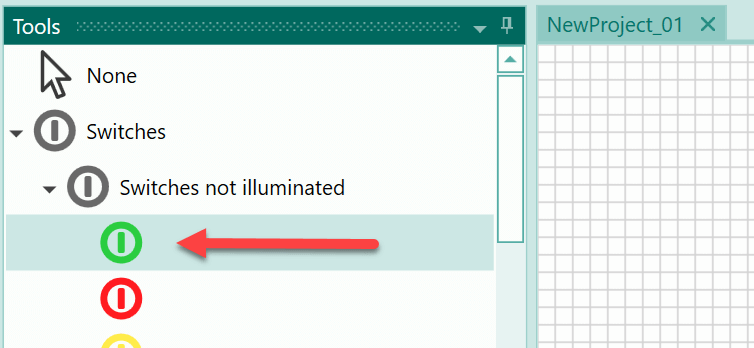
All operands you need are now available in the symbol table. The next step is to create the objects you need for the system on the PLC-Lab drawing board. In the example you need two push-buttons and a lamp. Start with the "Start" push-button. Within the tools, select the object type "Switches not illuminated":
Then move the mouse to the position within the drawing board where you want to place the switch. The mouse pointer now resembles a cross. Use the left mouse button to drag the switch object onto the drawing board. When you let go of the mouse button, the process is completed.
Tip
If you press the Shift key while dragging an object, the height and width of the object to be placed will be changed consistently.
In the next image, you can see the steps for placing the switch object; the Shift key was pressed while dragging the object:
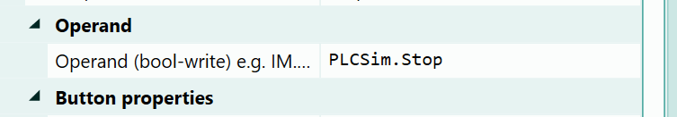
After the switch has been placed, its properties are displayed in the object properties table. In the example, the operand to which the switch object is connected should be specified first. It will be affected when the switch is actuated. Two options are available for specifying the operand:
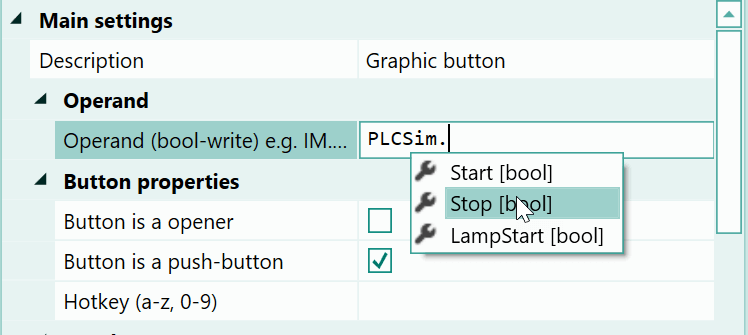
First option "Autocompletion": In the first option, in the cell for the operand, the device name followed by a period is specified first; in the example, this is "PLCSim.". Then use the key combination Ctrl + Space. As a result, all symbols of this device are now displayed in a list. Select the symbol you want to use with the cursor keys (up or down) and confirm with the return key. The selected symbol is then entered as an operand. These steps are shown below:
Second option "drag & drop": With the second option, you select the line of the operand in the symbol table and then drop it on the description of the operand property using drag & drop.
Third option "Drag & Drop" on the Object: Now for the third option. In this case, you also select the operand from the symbol table and then drag and drop it. But here the target is the switch. This means that the operand is dropped directly on the object. For switch objects, the operand you have inserted is automatically inserted as the operand that is affected by the switch.
Info
The advantage of the options 2 and 3 is that the symbol of the operand is automatically used to label the switch object.
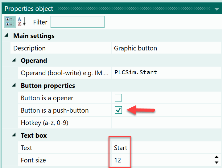
When you have used one of the options, the switch is connected to the symbol "Start" and thus to the I0.0. Now the switch object must be defined as a push-button. Furthermore, "Start" should appear as text with a font size of "12" in the switch object. The properties required for this are shown below:
Drawing the second push-button
And now to the second switch. We want to create this switch from a copy of the first switch. Select the first switch and press Ctrl + D. A copy of the selected switch is then placed next to the source object.

To display the properties of the new switch in the table, click on a free space in the draw-window and then select the new switch with the mouse. Now the properties are displayed and can be changed. In the first step you have to adjust the operand of the switch. Because this should be the "Stop" push-button. In the property for the operand, remove the characters behind the device name "PLCSIM". and use the Ctrl + Space keys:
From the list, you can now select and insert the "Stop" symbol.
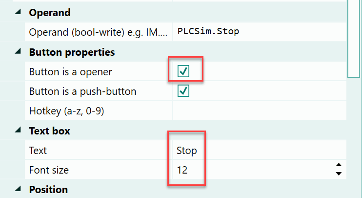
This connects the "Stop" push-button to the correct operand. The push-button must be designed as an opener, which means that it provides the status '0' to the operands when actuated and the status '1' when idle. Furthermore, the text in the switch object should read "Stop". These changes are shown below.
Drawing a lamp
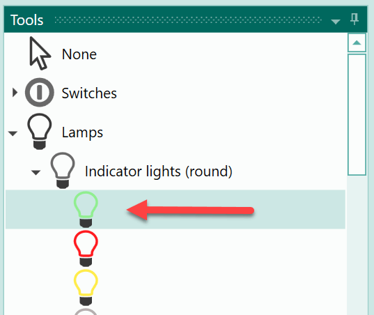
Finally, we need a lamp object to signal the state "Start". For this purpose, select a green indicator light in the object selection "Lamps->Indicator lights".
The lamp can then be placed on the drawing board.
In the next step, assign the operand with the symbol "LampStart" to the object.

You can remove the caption from the lamp.
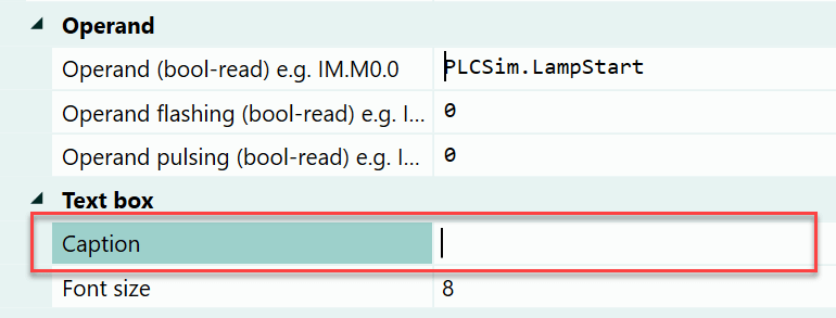
This means that no more text is displayed in the object.
After these actions, the drawing board looks as follows:
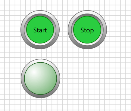
All objects are available for the example. If required, you can save the layout by pressing Ctrl + S.
Using the Siemens TIA Portal
In the example, we want to test the PLC program of an S7-1200 or S7-1500 in PLC-Lab. This means that we have to use the Siemens TIA Portal. The possible TIA versions are:
- V13
- V14
- V15
- V16
- V17
- V18 (as of PLC-Lab V2.3.0.0)
- V19 (as of PLC-Lab V2.5.0.0)
Within the TIA Portal, the PLC program is to be processed via the PLCSIM for the S7-1200/1500. In other words, we don't need a real PLC for the test.
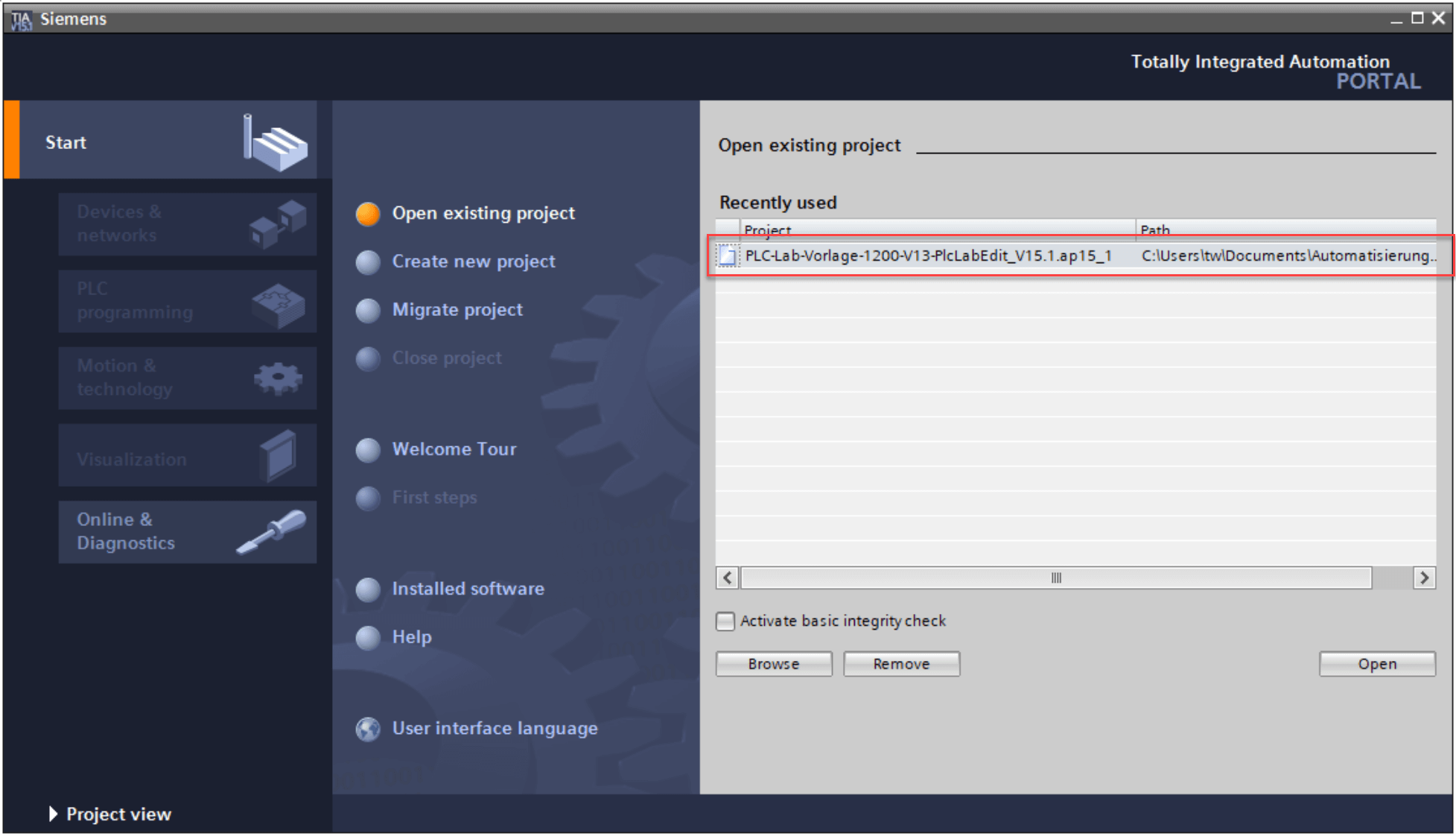
After starting the TIA Portal, load the PLC-Lab template project. In the example, we will simulate the program for an S7-1200, which is why we have to open the template project for an S7-1200. If you want to use the PLCSIM for the S7-1500, open the template project for the S7-1500.
Info
Note: If PLC-Lab is to be connected to the PLCSIM of the S7-1200/1500, the template project of the S7-1200 or S7-1500 is required. Otherwise there will be no connection between PLC-Lab and the Siemens PLCSIM. When PLC-Lab is installed, the template projects are stored in the user's documents in the "Automation\PLC-Lab Editor\" directory.
Info
Note: If an existing TIA project is to be simulated with PLC-Lab, refer to the following link for the procedure: Test an existing TIA project with PLCSim 1200/1500 and PLC-Lab
Below you can see the selection of the template project for the S7-1200:
Depending on which TIA version is used, it may be necessary to upgrade the project once, as each TIA version has its own project format. Note that it is not possible to open a project with an older TIA version. So you cannot open a V15 project with TIA PORTAL V14.
After the template project has been opened, you can change to the project view by pressing the following button in the TIA:

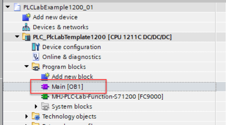
In the project view, use the menu item "Project->Save as" so that a copy of the template project is saved under a different name. This should be done so that the PLC-Lab template project is not changed. For example, "PLCLabExample1200_01" can be used as the name for the new project.
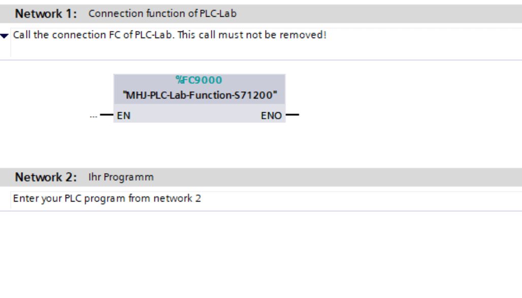
The PLC program for the example is to be programmed in OB1. This already exists in the project and can be opened with a double click.
The connection function of PLC-Lab must be called in network 1 of OB1. You can add your own PLC program in network 2.
In the example, the PLC program consists of an SR memory whose S input is assigned the input I0.0 and the R input is assigned the input I0.1. The SR memory itself has the operand Q0.0. The definition of the operands was already carried out in PLC-Lab, because there the objects were linked together with these operands. The following image shows the PLC program:
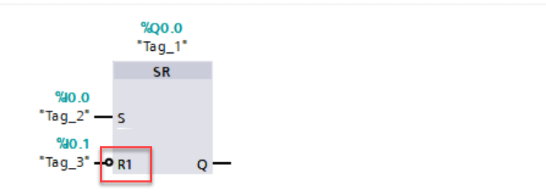
It should be noted that a negation must be attached to the R input, since the "Steuerung Aus" push-button has been designed as an opener and thus supplies the value '0' when actuated. The program is now complete and can be saved.
In the next step, you start the simulation by clicking the following button:
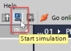
Then follow the instructions of the TIA until the PLCSIM window is displayed.
PLCSIM in TIA Portal V13 to V17
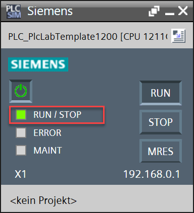
The simulation PLC must be in RUN state for the PLC program to be processed. Below is the representation of PLCSIM in which PLCSIM is in run.
You can then switch to PLC-Lab.
PLCSIM in the TIA Portal as of V18
Important
For V18 of the TIA portal, at least version 2.3.0.0 of PLC-Lab must be used. Within the settings of the PLCSIM device, V18 must be set as the target version of the TIA. For V19 of the TIA portal, at least version 2.5.0.0 of PLC-Lab must be used. Within the settings of the PLCSIM device, V19 must be set as the target version of the TIA.
The simulation PLC must be in RUN state for the PLC program to be processed. Below is the representation of PLCSIM in which PLCSIM is in run.
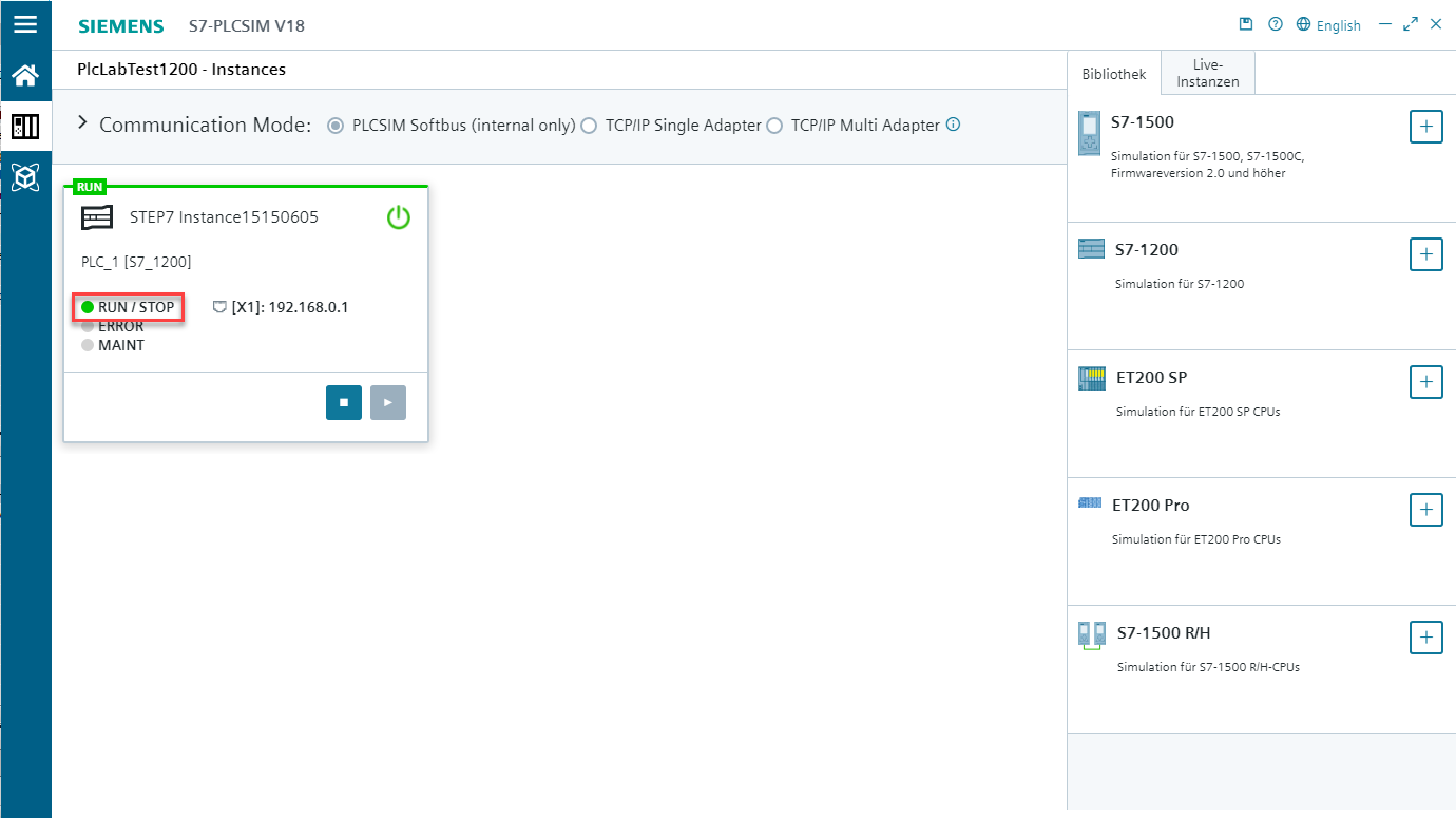
You can then switch to PLC-Lab.
Info
If an S7-1500 with the licence type "Advanced" is used in PLCSIM V18 or higher, then it is a PLCSIM-Advanced instance. This is then to be addressed via the device "PLCSIM-Advanced" in PLC-Lab. Siemens PLCSIM Advanced
Activating the simulation in PLC-Lab
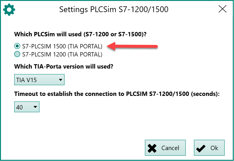
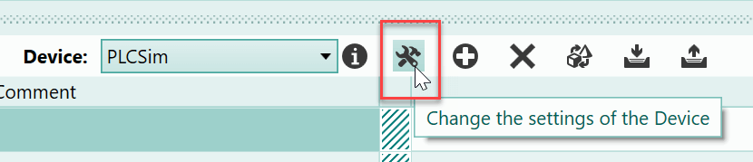
Before PLC-Lab is switched to run mode, the PLCSIM must be set to S7-1200. You only have to do this once if you don't intend to use the layout for the S7-1500 later. To do this, set the device selection in the upper part of the symbol table to "PLCSim" and click the button for "Changes the settings of the Device".
You will then see the dialog "Settings PLCSim S7-1200/1500". In this dialog "Which PLCSim will used" is set to the S7-1200. In addition, you should pre-select the TIA version you are using in the dialog. Only if no connection is established with the explicit setting of the TIA version, the selection "Universal" should be used.

Info
If a TIA version V19 or higher is selected, the so-called speed-up level can also be selected. The values 0, 1 and 2 can be set here. The value 0 has no effect. With values 1 and 2, the connection protocol between PLC-Lab and PLCSIM is accelerated. However, this can also result in no communication being established. If no connection can be established between PLC-Lab and PLCSIM, the acceleration factor should be reduced.
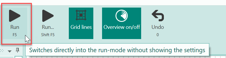
Now all prerequisites are met. You can start the simulation in PLC-Lab via the RUN button.
PLC-Lab will then attempt to establish the connection to the PLCSIM of the TIA. The first connection setup takes slightly longer (approx. 30 seconds). During this time, the PLC-Lab status bar indicates that the search is running.
Once the connection has been established, the display changes as follows:

Testing the PLC program
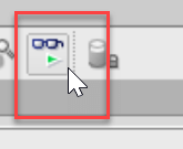
Now you can switch to the TIA and enable OB1 observation by pressing the mouse button shown below:
Then the display of OB1 changes and the status data of the block is displayed. You can now switch the push-buttons to PLC-Lab and observe the effects in OB1.
You can see that when the "Steuerung Ein" push-button is pressed, output Q0.0 is set to status '1' and the lamp lights up as a result. When the "Steuerung Aus" push-button is activated, Q0.0 is reset and the lamp turns dark again.
Conclusion
The example shows how a virtual system can be created in PLC-Lab to test a PLC program that is processed in PLCSIM S7-1200/1500 in the TIA portal. In the example, we used the PLCSIM of the S7-1200. If you want to use the PLCSIM of an S7-1500, you have to use the PLC-Lab template for the S7-1500 in the TIA portal. Within PLC-Lab, the S7-1500 is then selected in the settings for the device "PLCSim".