Program CODESYS based PLCs directly with Grafcet DIN EN 60848
Info
You need Grafcet-Studio Pro/Demo V1.1.0.0 or newer
Note: CODESYS, CODESYS logo: © 2019 3S-Smart Software Solutions GmbH, CODESYS Website
![]()
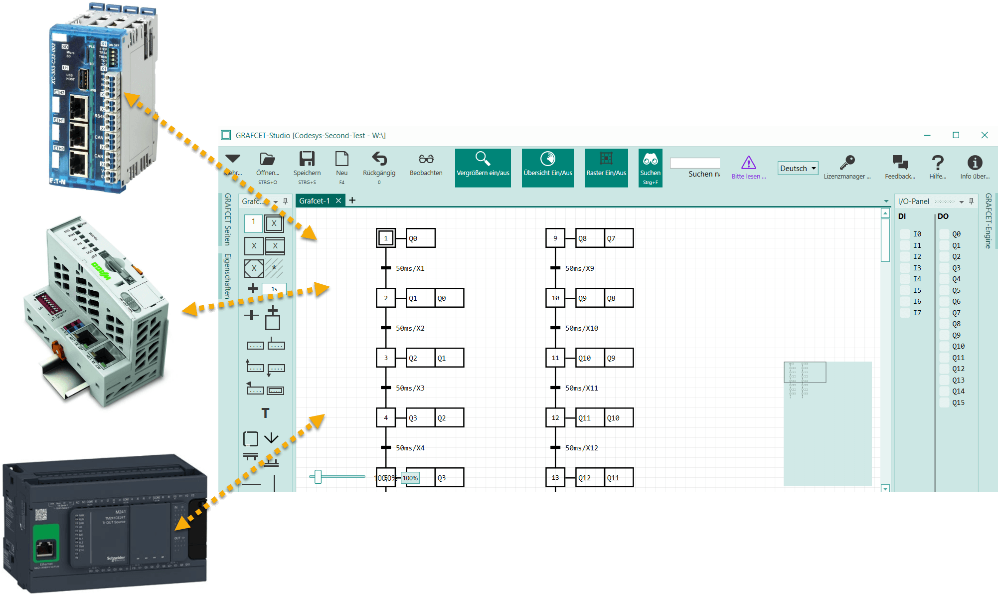
To program a CODESYS V3 based controller with Grafcet-Studio, we deliver the Grafcet-Engine as CODESYS V3 Library (compiled library). The Grafcet engine supports a maximum of 100 steps in the CODESYS variant. If you need more than 100 steps, please send us an email to support@mhj.de. The Device must be a CODESYS V3 based Device. At least 64 KB of remanent memory must be available. The device must support OPC/UA.
Downloads
| Link | Description | Size in MB |
|---|---|---|
| Download | CODESYS Compiled Library (CODESYS Compiler Version: 3.5.3.86) with the Grafcet Engine Version 0x1011. This library must be installed into the library repository. Then you can insert the library into your project. | 0.1 MB |
| Download | CODESYS template project (V3.3SP1) as basis for your CODESYS project. To use the Grafcet engine, only a few components (variables, FB) are required that are available in this project. | 0.1 MB |
| Download | Project template as PDF file. If the template project cannot be opened. | 0.2 MB |
| Download | Grafcet-Studio Test Project (3 Steps) | 0.1 MB |
| Download | XSOFT-CODESYS (3.5.12) Example project for Eaton controllers. If you own XSOFT-CODESYS, use this project as a template project. | 0.2 MB |
| Download | WAGO eCockpit V1.5.0.3 Example project for WAGO controllers. If you own WAGO eCockpit, use this project as a template project. | 0.2 MB |
Preparations for the CODESYS project:
- Installation of the library Grafcet-Engine1x.compiled-library (see Download above)
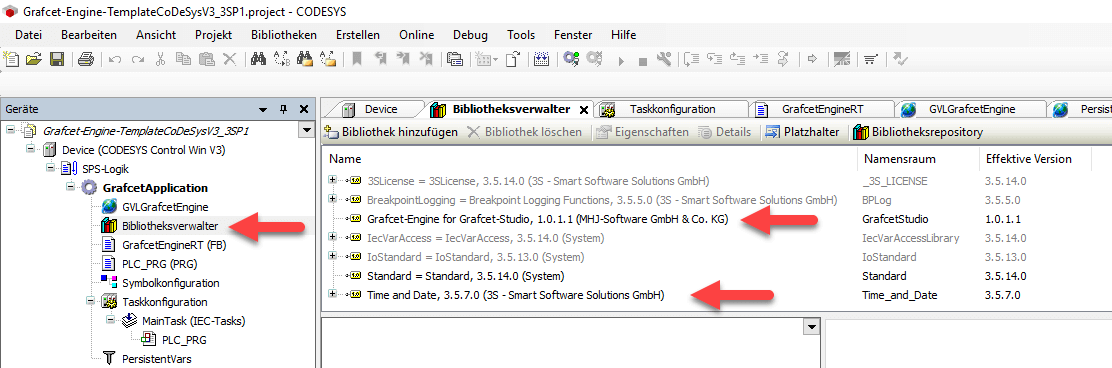
- Open the CODESYS template project Grafcet-Engine-TemplateCoDeSysV3_3SP1.project (see download above). Replace the Device "CODESYS Control Win V3" with your hardware PLC and configure the modules.
- Alternative: Create a project with your CODESYS tool and configure the hardware. Then start a 2nd instance of the CODESYS tool and open the template project. Then you can copy and paste (CTRL+C and CTRL+V) the necessary components into your project.
- Add the library Grafcet-Engine for Grafcet-Studio (namespace: GrafcetStudio) to your project
- Add the library Date and Time (this is a buildin CODESYS standard library)
This could cause problems if your CODESYS version is too old. Then you may not be able to import the library or open the template project. If possible, you should update your CODESYS programming tool. Contact us at support@mhj.de if you need help.
Important settings in the CODESYS project:
- Open the symbol configuration by double-clicking and make sure that the variable "GVLGrafcetEngine" is published via OPC/UA (is there a check mark?).
- The I/O modules to be used via the Grafcet logic must be configured: Module setting local I/O image of the module Setting "Update variables" to Activated 2 (always in bus cycle task). This can be implemented globally in the PLC settings or separately for each module.
Preparations at Grafcet Studio:
A new CODESYS Device must be created:
- Create a new Device of type "OPC/UA Device"
- Define connection parameters: IP address, OPC/UA port (default=4840), instance variable container (default=GVLGrafcetEngine), instance variable (default=GrafcetEngineRuntime). Here you normally only have to change the IP address.
- Define IO mapping: The Grafcet engine is informed which I/Os are to be used in the PLC.
Image Codesys V3 Add Device:
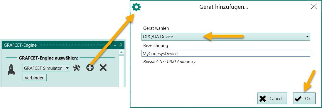
Image Connection settings:
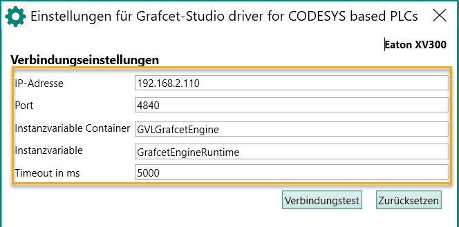
The field Instancevariable Container must contain the name of the global variable table in which the Grafcet instance is stored. The field Instancevariable must contain the variable name of the GrafcetEngine instance. If you have not changed the source code, the correct names are already entered here.
Picture: IO mapping:
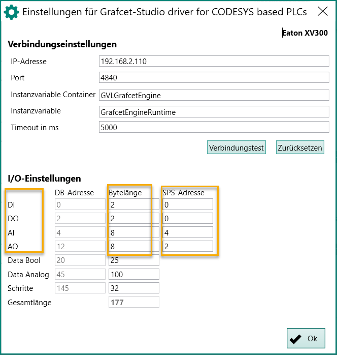
Example in picture: These addresses are to be used in the PLC:
- 16 digital inputs: address 0-1 (%IB0,%IB1)
- 16 digital outputs: Address 0-1 (%QB0,%QB1)
- 4 analog inputs: Word address 4-7 (%IW4,%IW5,%IW6,%IW7)
- 4 analog outputs: Word address 2-5 (%QW2,%QW3,%QW4,%QW5)
The I/O settings must then be set:
- DI: Byte length=2 for 16 DI, PLC address=start address=0
- DO: Byte length=2 for 16 DO, PLC address=start address=0
- AI: Byte length=8 for 4 AI, PLC address=start address=4
- AO: Byte length=8 for 4 AO, PLC address=start address=2
Hints: For the individual ranges DI, DO, AI, AO only 1 range can be defined at a time. This means: If, for example, the DI modules are spread on the PLC at addresses 0-1 and 10-11, then only 1 area with Grafcet Studio can be used.
With these settings you have set the start address of the I/O. Now simply insert the symbols in the correct order into the symbol table. The individual symbols are then addressed automatically from top to bottom. If individual bits of a byte are not used for Boolean symbols (Boolean operands), simply create placeholders for symbols (Reserved1, Reserved2, etc.). Alternatively, you can also define a gap. Simply enter "{#3}}" in the comment column, for example. This means that at least 3 bits should be used for the symbol. The next symbol is then addressed accordingly (see following figure: after I0.2 follows I0.5). You can also use Drag&Drop to move individual symbols to another line. See the following picture:
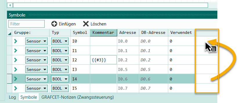
Use the 1st unused column for Drag&Drop, as shown in the picture.
Once these steps are completed, Grafcet-Studio can access the controller via OPC/UA:
- Load the Grafcet logic to the Device
- Monitoring the Grafcet logic
The Grafcet then runs independently (like any other PLC program). The CODESYS programming system is no longer necessary for programming in Grafcet. It also does not have to be installed on the PC. In addition to the Grafcet logic, a program written in ST, for example, can be placed in the controller, which can exchange data with the Grafcet logic if required.
Test with Grafcet Studio
When you've prepared everything, you can do a first test.
Check again:
- The project with the Grafcet Engine is in the PLC.
- A new device has been created in Grafcet Studio and the IP address and I/O mapping are set correctly.
- The PLC settings local I/O image of the module, "Update variables" are set to Activated 2 (always in bus cycle task).
- The variable table GVLGrafcetEngine is published in the symbol configuration.
- The IP address of the PLC is in the same network as the IP address of the PC.
The 1st test (see also following picture):
- Press the Connect button in the Grafcet Engine window.
- A connection should now be established. The counters (picture point 4) should count up.
- Press the button Write (picture no. 6) to write the graphcet into the device.
- Now the first 3 outputs should switch on and off one after the other.
- If you press the Watch button (see tool bar, icon with the glasses), you will see the Grafcet in Watch mode.
- Apply voltage to the PLC at the 1st input. Then the symbol I0 should be highlighted in color in the I/O Panel (see picture point 8).
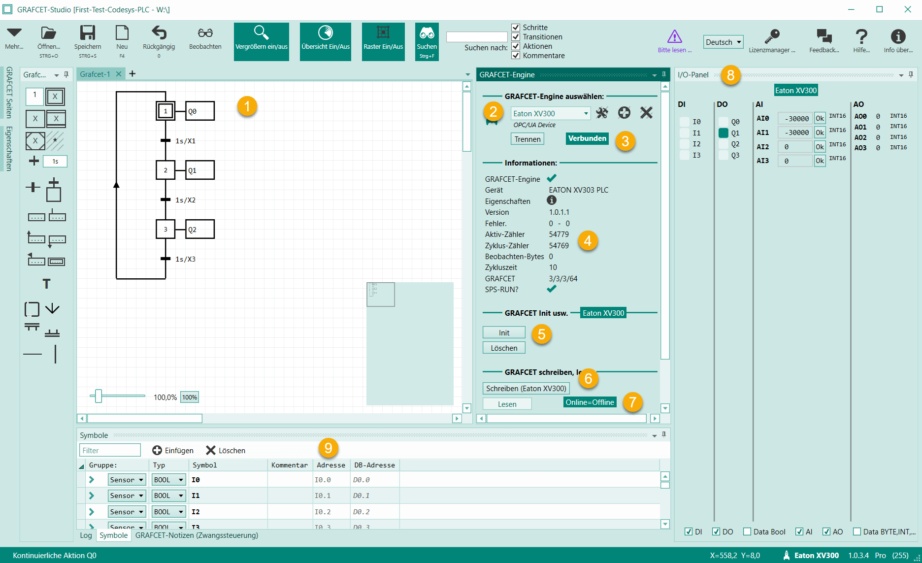
| No | Description |
|---|---|
| 1 | The first 3 outputs are switched on one after the other. |
| 2 | The newly created Device is set up |
| 3 | The connection has been established |
| 4 | These counters have to count up, then the Grafcet engine works correctly. |
| 5 | Button Init=Activate all initial steps, Button Delete=Delete Grafcet program on Device |
| 6 | Button Write=Write graphcet to the Device |
| 7 | Advertisement Offline matches Online. |
| 8 | The I/O Panel displays the current states of the I/Os (if a connection exists) |
| 9 | Important: Check here in the symbol table whether the I/O addresses are set correctly. See column Address. |
If you have any problems with this test, please contact our support by email: support@mhj.de
Explanation of the template project
Library "GrafcetEngine"
The library Grafcet-Engine1x.compiled-library was imported so that the namespace "GrafcetStudio" is useable.
Global Variable Table "GVLGrafcetEngine"
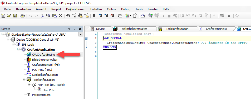
In this variable table, the instance GrafcetEngineRuntime is created, which is used in the FB GrafcetEngineRT.
FB "GrafcetEngineRT"
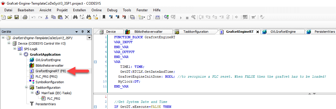
This FB calls the Grafcet engine and passes a millisecond counter and the current date and time. Furthermore, the Grafcet program is written into a persistent variable after a Grafcet program has been retransmitted. At a restart, the saved Grafcet program is loaded from the persistent variable. Thus the Grafcet program is immediately available after switching on the device.
Program "PLC_PRG"
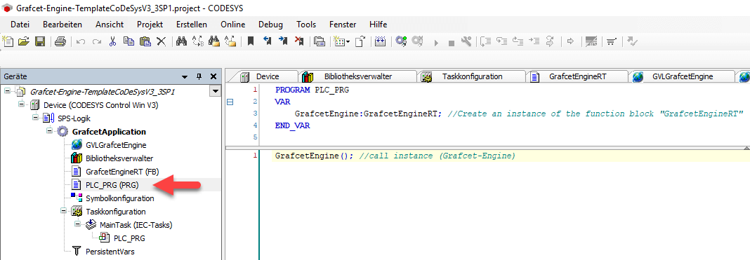
In the main program, an instance of GrafcetEngineRT is created and called.
Persistent variable table "PersistentVars"
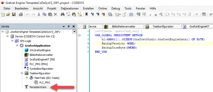
Here the Grafcet program is saved remanently. This requires approx. 63 KB of remanent memory. Remark: The attempt to store the Grafcet variables exclusively in a remanent table did not lead to success, because the data exchange via OPC/UA did not work anymore.
Symbol configuration
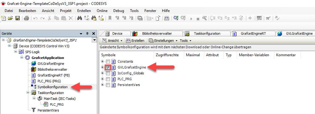
In the symbol configuration, the table GVLGrafcetEngine must be published via OPC/UA. This is automatically the case when "GVLGrafcetEngine" is checked.
Task configuration
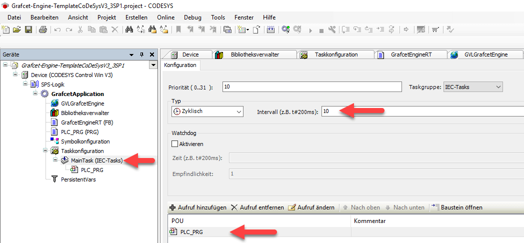
An interval of 10ms is sufficient for the Grafcet engine.
Local I/O image setting
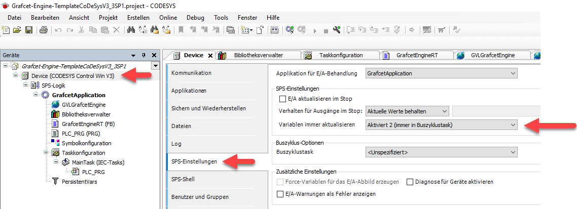
The setting local I/O image of the module, "Update variables" must be set to Activated 2 (always in bus cycle task). Or you can set each assembly separately to this value. This setting is necessary because the Grafcet engine accesses the I/O via pointers. If this setting is not active, the Grafcet engine cannot synchronize the I/O.
Communication settings
Info
If this error message appears in Grafcet-Studio when connecting: Endpoint does not support the user identity type provided. Then you have to switch on the anonymous login option.
Starting CODESYS V3.5.17 the user management is forced active. In order for Grafcet-Studio to be able to log in, you must disable it. Go to Communication in the Device Settings. Click on Device in the upper right corner to open the context menu. Select the menu item Change communication policy. Here you can enable Allow anonymous login.
Read and write Grafcet symbols in the PLC program
It is also possible to write your own code additionally to the Grafcet program and to carry out a data exchange with the Grafcet program. Thus it is possible to influence the conditions of the transitions, or to react to actions.
For data exchange, the Grafcet Engine provides functions (FC) that allow you to read and write values (symbols) from the Grafcet logic. These functions always expect the instance of the GrafcetEngine and the offset address of the symbol, which you can read in the symbol table in Grafcet-Studio in the column DB-address.
Functions to be able to read and write Grafcet symbols:
| Symbol data type | Read function | Write function |
|---|---|---|
| BOOL | "GetGrafcetSymbolBool"(GrafcetEngineInstance:=GVLGrafcetEngine.GrafcetEngineRuntime, Offset := 175, Bit:=1); | "SetGrafcetSymbolBool"(GrafcetEngineInstance:=GVLGrafcetEngine.GrafcetEngineRuntime, Offset := 175, Bit:=1, Value:=true); |
| UInt8 | "GetGrafcetSymbolUInt8"(GrafcetEngineInstance:=GVLGrafcetEngine.GrafcetEngineRuntime, Offset := 175); | "SetGrafcetSymbolUInt8"(GrafcetEngineInstance:=GVLGrafcetEngine.GrafcetEngineRuntime, Offset := 175, Value=4); |
| UInt16 | "GetGrafcetSymbolUInt16"(GrafcetEngineInstance:=GVLGrafcetEngine.GrafcetEngineRuntime, Offset := 175); | "SetGrafcetSymbolUInt16"(GrafcetEngineInstance:=GVLGrafcetEngine.GrafcetEngineRuntime, Offset := 175, Value=4); |
| Int16 | "GetGrafcetSymbolInt16"(GrafcetEngineInstance:=GVLGrafcetEngine.GrafcetEngineRuntime, Offset := 175); | "SetGrafcetSymbolInt16"(GrafcetEngineInstance:=GVLGrafcetEngine.GrafcetEngineRuntime, Offset := 175, Value=4); |
| Int32 | "GetGrafcetSymbolInt32"(GrafcetEngineInstance:=GVLGrafcetEngine.GrafcetEngineRuntime, Offset := 175); | "SetGrafcetSymbolInt32"(GrafcetEngineInstance:=GVLGrafcetEngine.GrafcetEngineRuntime, Offset := 175, Value=4); |
| Float | "GetGrafcetSymbolFloat"(GrafcetEngineInstance:=GVLGrafcetEngine.GrafcetEngineRuntime, Offset := 175); | "SetGrafcetSymbolFloat"(GrafcetEngineInstance:=GVLGrafcetEngine.GrafcetEngineRuntime, Offset := 175, Value=4); |
Example:
In this example, Grafcet symbols are first set to a certain value and then read out again.
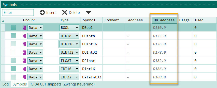
These Grafcet symbols were created in Grafcet Studio in the symbol table:
| Symbol Group | Symbol Data Type | Symbol Name | DB Address |
|---|---|---|---|
| Data | BOOL | DBool | 150.0 |
| Data | UINT8 | DUint8 | 175 |
| Data | UINT16 | DUint16 | 176 |
| Data | UINT32 | DUInt32 | 178 |
| Data | FLOAT | DFloat | 182 |
| Data | INT16 | DInt16 | 186 |
| Data | INT32 | DInt32 | 188 |
Info
The DB address column of the symbol table is important here. This address must be passed to the function "GetGrafcetSymbol..." or "SetGrafcetSymbol...".
Picture:
ST Test program in program PLC_PRG: Variable declaration:
    testbool:BOOL;
    testuint8:BYTE;
    testuint16:WORD;
    testuint32:DWORD;
    testint16:INT;
    testint32:DINT;
    testReal:REAL;
Code area:
//Write values
GrafcetStudio.SetGrafcetSymbolBool(GrafcetEngineInstance:=GVLGrafcetEngine.GrafcetEngineRuntime, Offset:=150, Value:=TRUE, BitNr:=0);
GrafcetStudio.SetGrafcetSymbolUInt8(GrafcetEngineInstance:=GVLGrafcetEngine.GrafcetEngineRuntime, Offset:=175, Value:=233);
GrafcetStudio.SetGrafcetSymbolUInt16(GrafcetEngineInstance:=GVLGrafcetEngine.GrafcetEngineRuntime, Offset:=176, Value:=32000);
GrafcetStudio.SetGrafcetSymbolUInt32(GrafcetEngineInstance:=GVLGrafcetEngine.GrafcetEngineRuntime, Offset:=178, Value:=200000);
GrafcetStudio.SetGrafcetSymbolFloat(GrafcetEngineInstance:=GVLGrafcetEngine.GrafcetEngineRuntime, Offset:=182, Value:=601.23);
GrafcetStudio.SetGrafcetSymbolInt16(GrafcetEngineInstance:=GVLGrafcetEngine.GrafcetEngineRuntime, Offset:=186, Value:=-32000);
GrafcetStudio.SetGrafcetSymbolInt32(GrafcetEngineInstance:=GVLGrafcetEngine.GrafcetEngineRuntime, Offset:=188, Value:=-300000);

//Read values
testbool:=GrafcetStudio.GetGrafcetSymbolBool(GrafcetEngineInstance:=GVLGrafcetEngine.GrafcetEngineRuntime, Offset:=150, BitNr:=0);
testuint8:= GrafcetStudio.GetGrafcetSymbolUInt8(GrafcetEngineInstance:=GVLGrafcetEngine.GrafcetEngineRuntime, Offset:=175 );
testuint16:=GrafcetStudio.GetGrafcetSymbolUInt16(GrafcetEngineInstance:=GVLGrafcetEngine.GrafcetEngineRuntime, Offset:=176);
testuint32:=GrafcetStudio.GetGrafcetSymbolUInt32(GrafcetEngineInstance:=GVLGrafcetEngine.GrafcetEngineRuntime, Offset:=178);
testReal:=GrafcetStudio.GetGrafcetSymbolFloat(GrafcetEngineInstance:=GVLGrafcetEngine.GrafcetEngineRuntime, Offset:=182);
testInt16:=GrafcetStudio.GetGrafcetSymbolInt16(GrafcetEngineInstance:=GVLGrafcetEngine.GrafcetEngineRuntime, Offset:=186);
testInt32:=GrafcetStudio.GetGrafcetSymbolInt32(GrafcetEngineInstance:=GVLGrafcetEngine.GrafcetEngineRuntime, Offset:=188);
Check the values in Grafcet Studio: After the connection to the Device, the values can be checked either in the I/O panel or in the symbol table. The current values are displayed in the symbol table after the watch mode has been switched on. In the following picture the observation mode was switched on:
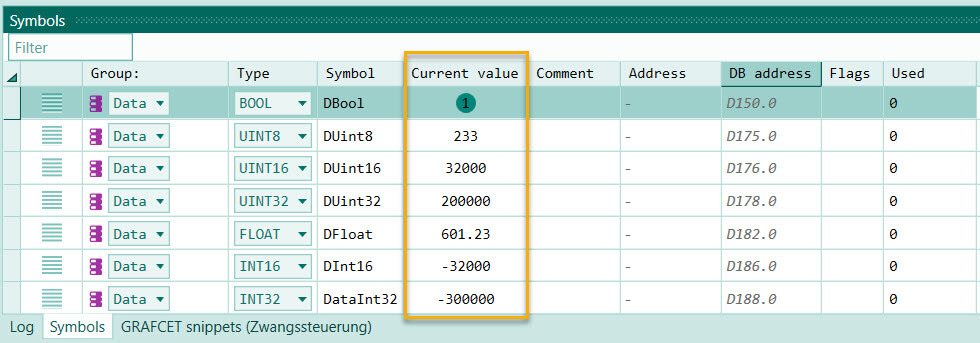
You can see that the values match the written values.
In this way you can now read out a Grafcet symbol in your own program and react to it. Or you can write a graphcet symbol in the "Data" area and then use this symbol in a transition.
Help with problems
There is no connection between Grafcet-Studio and the PLC? Please check:
- IP address set correctly?
- If you have changed the variable names: Is the information still correct in the connection settings in Grafcet-Studio?
- Is the variable GVLGrafcetEngine selected in the symbol configuration (check mark)?
- PC and PLC in the same network?
The states of the inputs are not recognized in the graph or the outputs do not arrive in the output module. Please check:
- In Grafcet-Studio: Check I/O mapping in the device settings. Are the start addresses of the inputs and outputs correct?
- CODESYS: Is the setting local I/O image of the module set to Activated 2 (always in bus cycle task)?
Contact our support if you cannot solve the problem yourself: support@mhj.de